
Protocol for calcium imaging of free-moving mice
1. Cranial window surgery
Chronic cranial window implantation was performed following a standard protocol with the following specific steps for two-photon microscopy. Mice were anesthetized with isoflurane (induction 4%, maintenance 2%) and secured in a stereotaxic frame.
-
The scalp was incised and retracted to fully expose the skull, which was then cleaned by removing all overlying periosteum and fascia using a scalpel blade. Shallow, parallel scratches were made on the skull surface to enhance the adhesion of the subsequent adhesive layer. The skull was thoroughly dried with a lint-free tissue.
-
A thin layer of cyanoacrylate adhesive (e.g., Vetbond or similar) was applied to the exposed skull and cured under a blue light for 30–60 seconds. This step creates a stable foundation, prevents periosteal regrowth, and minimizes infection, which can cause the cranial window to loosen and detach.
-
Using a mouse brain atlas as a guide, a circular region was marked on the skull over the primary visual cortex (V1) with a 3-mm transparent coverslip and fine-tipped forceps. A dental drill was used to carefully thin the skull along this circle. The drilling was stopped when the bone flap became noticeably mobile with light pressure from the forceps, indicating sufficient thinning without damaging the dura mater.
-
The skull surface was cleaned with a sterile saline-moistened cotton swab to remove bone dust and blood. Gelatin sponges (e.g., Gelfoam) were pre-cut and soaked in sterile saline for hemostasis. A single drop of sterile saline was applied to the thinned skull. With fine-tipped forceps, the circular bone flap was gently lifted by inserting the tip along the edge and pulling horizontally outwards. The bone flap was then quickly removed with the forceps.
-
Any oozing bleeding from vessels on the dura mater was immediately controlled with a piece of pre-moistened gelatin sponge. The area was rinsed with sterile saline from a 1-mL syringe to clear away blood.
-
If required, virus was injected at this stage using a polished glass micropipette loaded with approximately 200 nL of virus solution.
-
A custom-made cranial window, consisting of a 3-mm circular coverslip bonded to a titanium ring, was prepared. After sterilizing with 75% ethanol, the window was submerged in sterile saline.
-
The gelatin sponge was removed, and the custom window was placed over the exposed dura mater. A holding arm attached to a ceramic ferrule was used to gently press the coverslip against the dura while the titanium ring rested on the surrounding skull bone. Finally, the perimeter of the cranial window was sealed and bonded to the skull with cyanoacrylate adhesive.
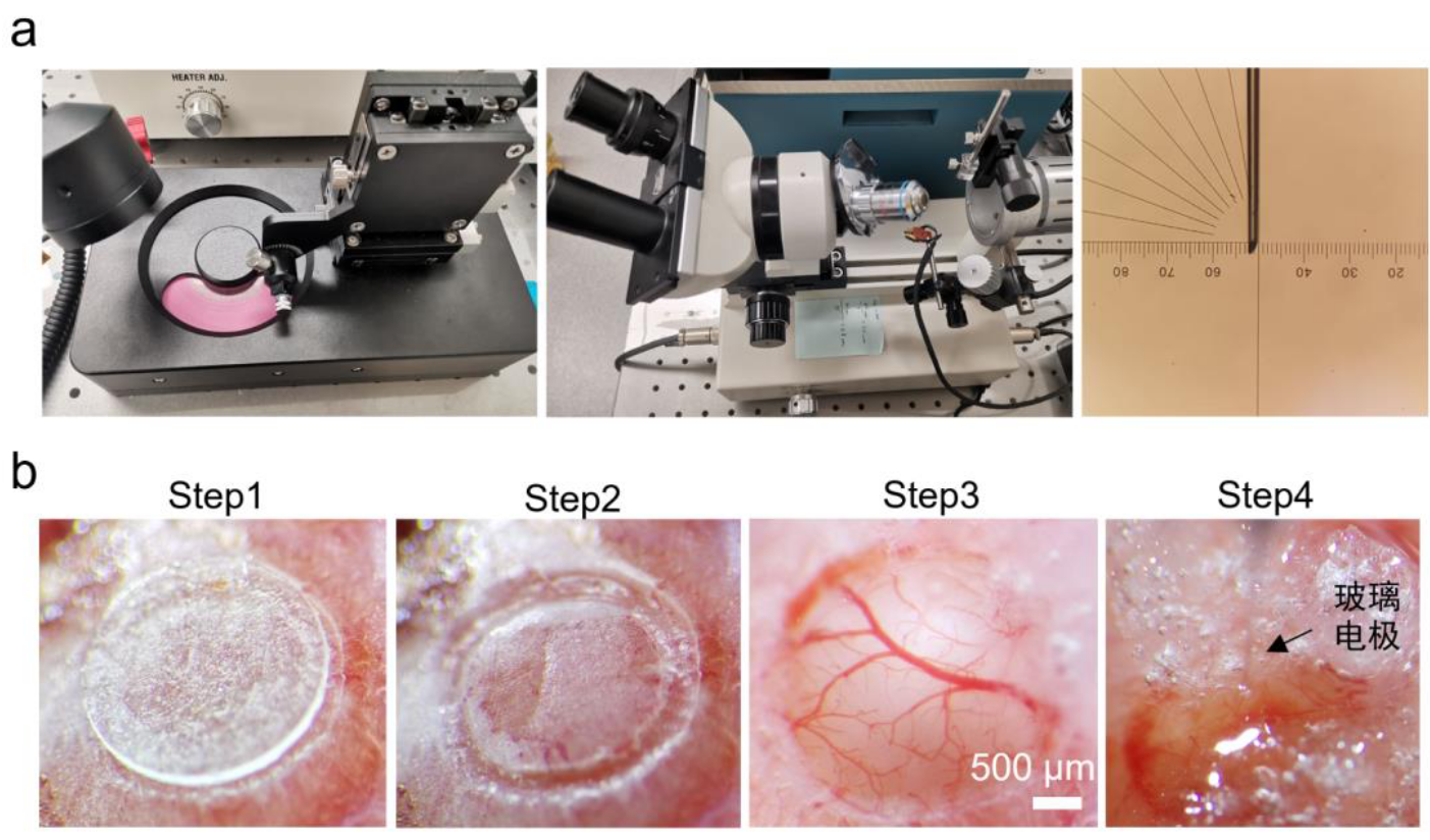
Figure 2.2 | Procedures for Chronic Cranial Window Implantation and Viral Injection in Mice. (a) The micropipette puller and its use. (b) Step-by-step procedure for chronic cranial window surgery and viral injection.
2. TPLSM
Two-photon microscopy experiments were conducted using an Olympus FVMPE-RS multiphoton laser scanning microscope (Olympus, Japan) equipped with an Olympus XLPLN25XWMP2 objective lens (25×, NA 1.05, working distance 2 mm). The system was coupled to a Spectra-Physics Insight X3 laser (Spectra-Physics, USA), which provided high peak power and a short pulse width of 120 fs, with a continuously tunable output wavelength from 680 to 1300 nm. Fluorescence was detected using highly sensitive GaAsP PMT detectors. A Leica SP8 DIVE multiphoton laser scanning microscope, featuring spectrally tunable PMT detectors, was also utilized for some experiments.
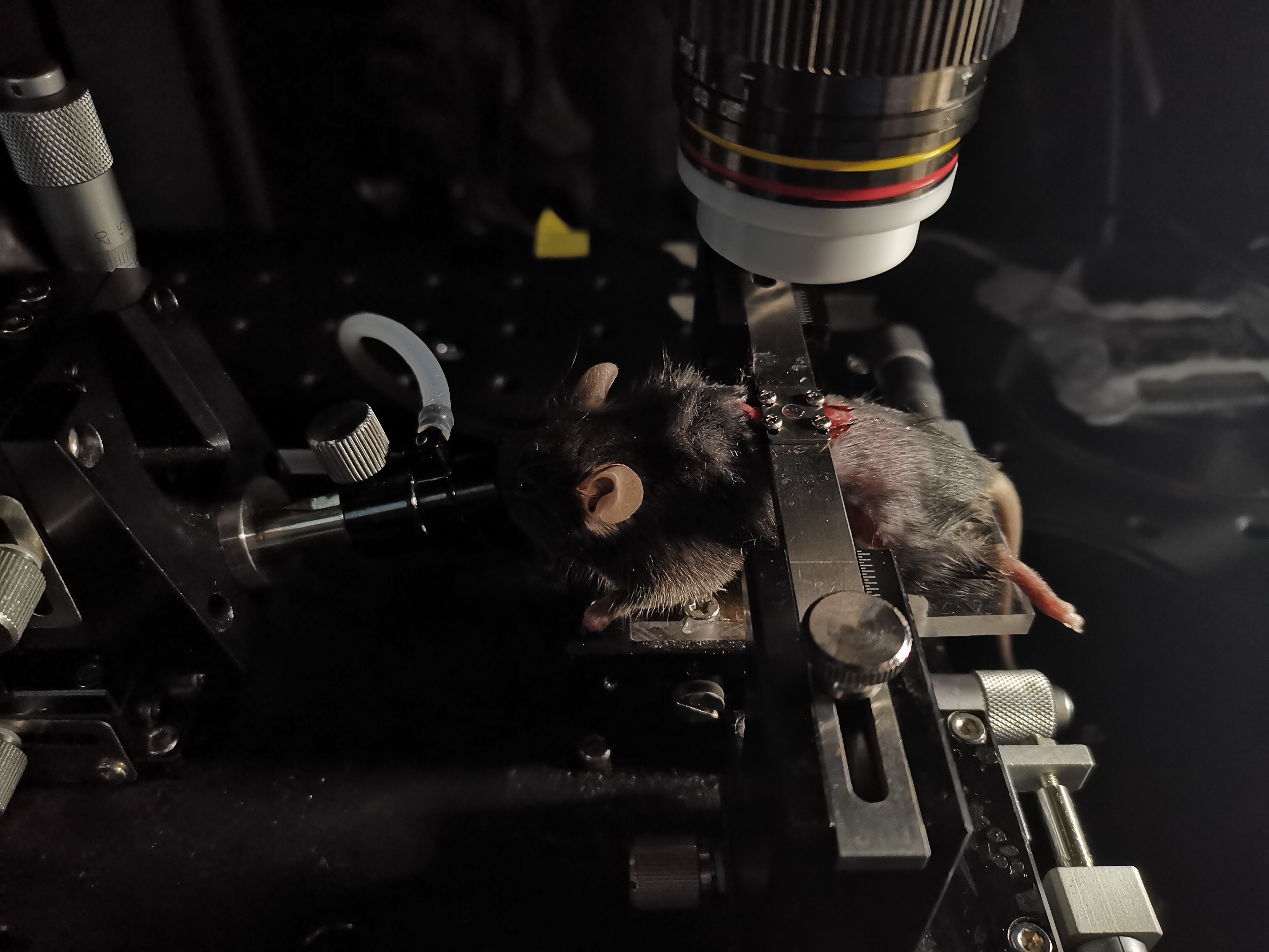
For imaging, mice were head-fixed under the objective lens while being placed on a free-moving treadmill. Prior to experiments, mice were repeatedly habituated to the head-fixed setup to minimize anxiety and stress-induced movement. A dual-head infrared camera mounted behind the objective lens was used to capture the mouse’s real-time activity during imaging (Fig. 2).
headfix system
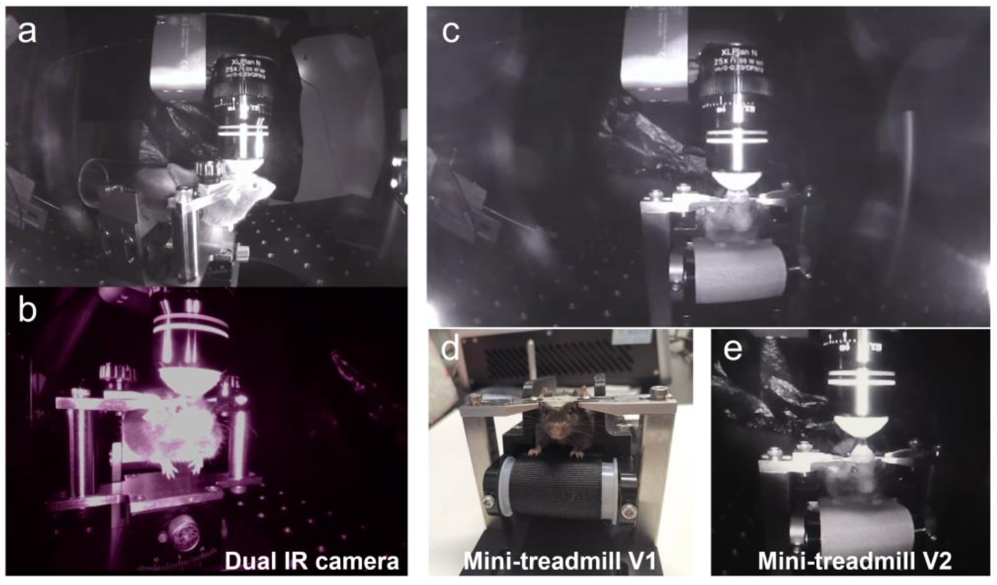
Figure 2 | Head-fixed setup for two-photon in vivo imaging of freely moving mice. (a-b) The first-generation setup consisted of an acrylic tube and a V-shaped head-holder mounted on a 2D optical breadboard, allowing the imaging plane to be adjusted perpendicular to the imaging light path. (c-e) The second-generation setup (Mini-treadmill V1, V2) replaced the acrylic tube with a miniature treadmill.
LightPath
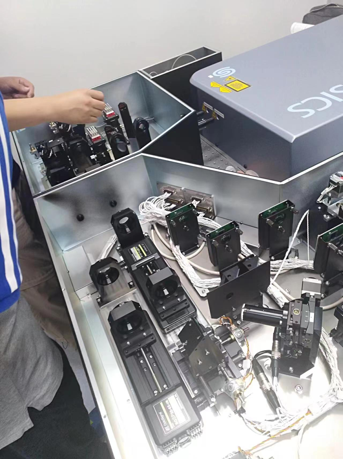
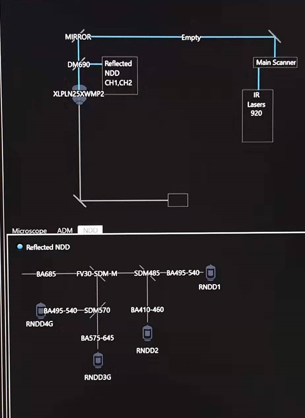
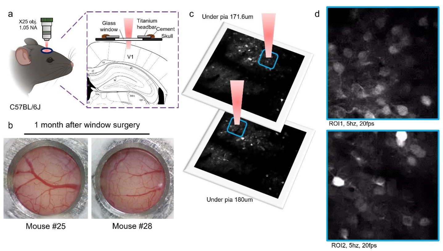
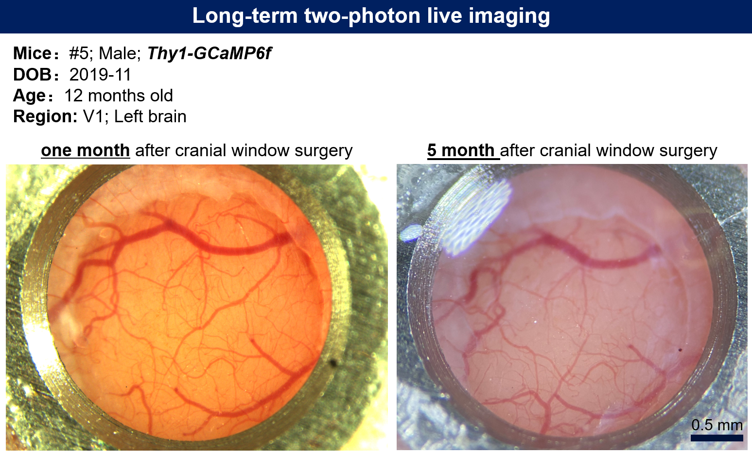
Figure 4 | Real-time imaging of neuronal activity in the primary visual cortex (V1). (a) Schematic of the cranial window surgery and two-photon imaging setup. (b) The cranial window one month after surgery, showing the long-term stability of the preparation. (c) Schematic of imaging regions at different z-axes. (d) Real-time imaging of neuronal activity captured at depths of 171.6 μm (ROI1) and 180 μm (ROI2) below the dura mater in the V1 cortex. The videos were acquired at a sampling frequency of 5 Hz and are played back at 20 fps. The green fluorescence intensity, derived from the genetically encoded calcium indicator GCaMP6f, reflects the intracellular calcium ion concentration.
Microvascular Hemodynamic Imaging
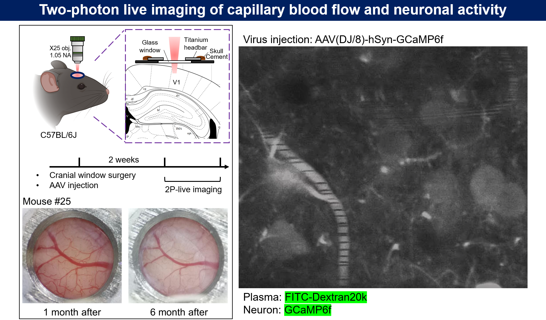
Microvascular hemodynamic imaging was performed as shown in Fig. 5. Experimental mice received an intravenous injection of 100 μL of Dextran-FITC plasma dye. The mice were then placed in the head-fixed setup under the two-photon microscope objective. After focusing, a target imaging region was selected. A single capillary was identified, and a short, straight segment of the vessel, aligned with the direction of blood flow, was selected for a time-series line scan (Fig. 6). The dye used in this experiment typically had a molecular weight of 2,000 kDa. Notably, 70 kDa Dextran-FITC is commonly used to detect changes in blood-brain barrier permeability.
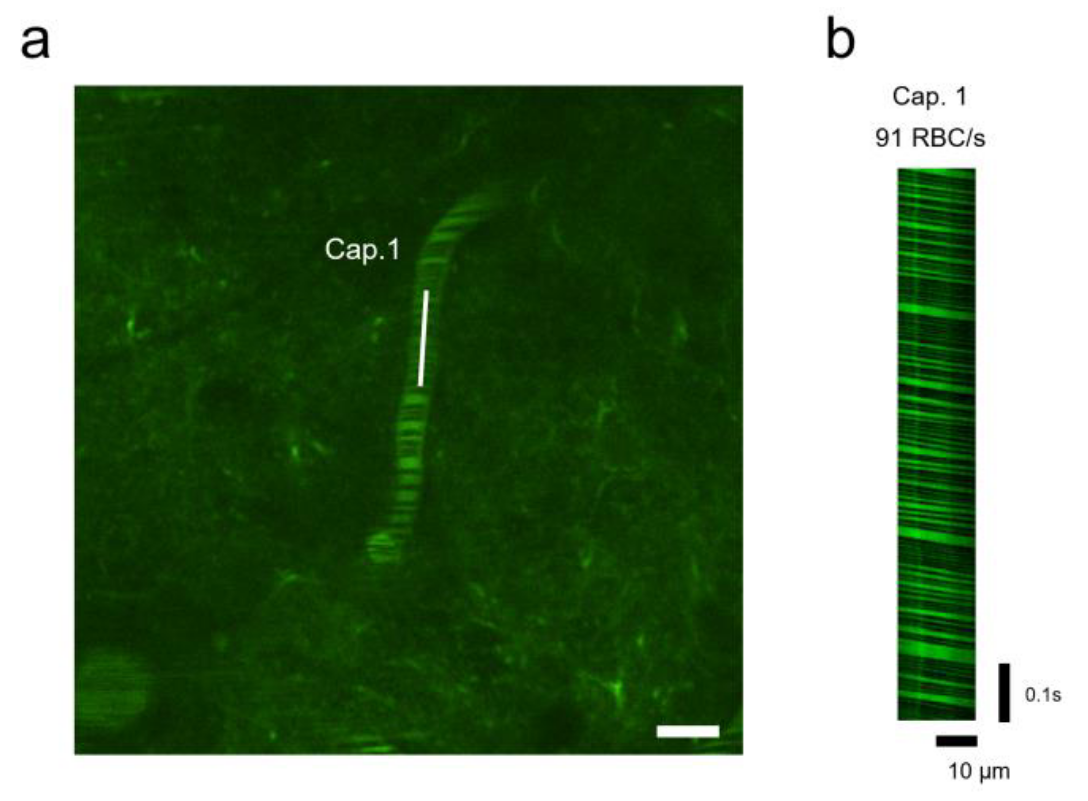
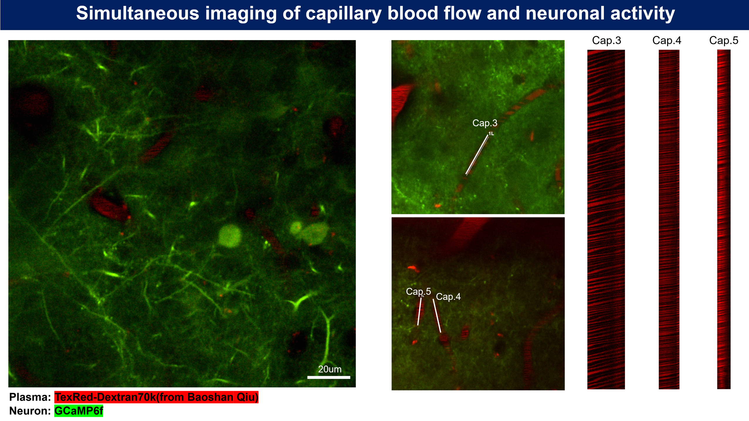
Figure 6 | Real-time hemodynamic imaging in the primary visual cortex (V1). (a) Plasma was fluorescently labeled with 2000 kDa Dextran-FITC (green fluorescence). A time-series line scan was acquired using a 920 nm excitation laser for 2000 frames. Scale bar, 10 μm. (b) A representative line-scan image from a targeted capillary in (a) showing a microvascular blood flow rate of 91 RBC/s. RBC, red blood cell.
Long-term two-photon imaging of spinal cord
 We use 10x objective (NA = 0.6) for imaging of spinal cord, as this objective has larger FOV and also maintain a relative high resolution during imaging.
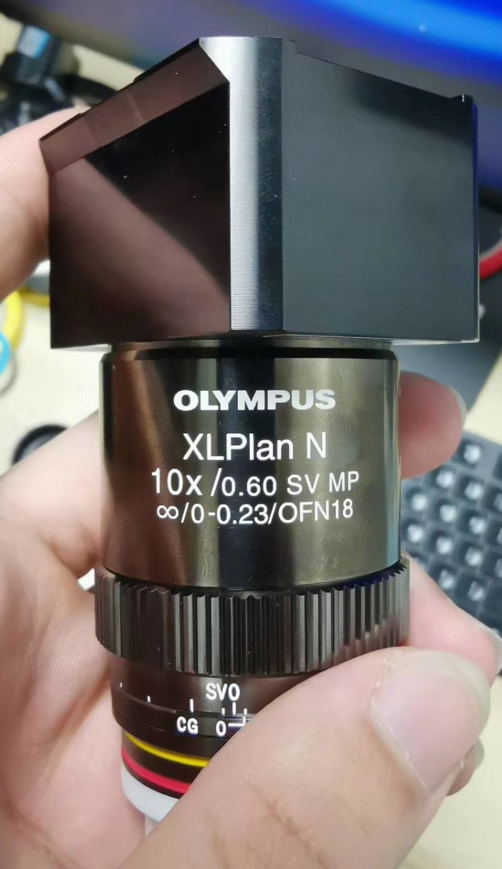
Working Distance: 8 mm
This is probably the longest focal length (180/10 = 18 mm) objective you can get and use with a standard two-photon system and see activity in single neurons. 0.6 NA might not be enough for tissue bulk labeled with OGB-1, but for GECIs like GCaMP6, signals from single cells are easily resolved.
3. Data analysis
softwares for 2p imaging data analysis:
- Motion correction: NoRMCorre Algorithm
4. Materials
-
Low-Friction Rodent-Driven Belt Treadmill [Janelia farm | Github]
Designed at HHMI’s Janelia research campus by the jET team, this treadmill is relatively small and inexpensive compared to most existing designs. It is manually driven with an encoder which tracks the movement of the belt. The encoder does not have to be connected, unless it is desired to record or analyze the motion. Encoder interfaces are documented in a separate repository and on Flintbox.